Max Residuals
|
This is used to match camera/marker combinations. The parameter sets the limit to the distance from the final location of the point in 3D and the intersecting camera ray. Any camera where it's ray is within this limit will be used for the final 3D transformation. The value will depend on the size of the volume. For volumes about 300-500 mm, a value between 1-3 is usually good, for 500-1000 mm between 3-5 and any larger than that use 5 and up. If the value is to large, you may end up with false 3D points and if it is to low, 3D points will not be calculated.
You can check the resulting residuals in the Stream3D Dynamic 3D view by hovering over a marker with the mouse while pressing the Ctrl key.
See Table
|
Predictor Window
|
A value larger than 0 will turn on the 3D point predictor. The predictor will estimate where each identified point will be found in the next frame and if found within the specified window size, the point will be considered part of the current point trajectory and will be assigned it's point number. Using the predictor will improve the performance since points will not have to be re-identified for each frame using Body Identification.
The size of the predictor window depends on the measurement volume and the size of the rigid body. The smaller the window is, the less chance that multiple points will be found within it's window thus minimizing errors due to incorrectly identified 3D points.
See Table
|
Acceleration Factor
|
The acceleration factor is part of the predictor extrapolation algorithm. The faster the movements, the higher the acceleration factor should be. A value of 5-20 should be adequate for "normal" motions.
|
Tracker Type
|
The MaxREAL uses 2 different type of Tracker/Body Identification routines.
M3 Tracker
|
This tracker uses rigid bodies with 3 markers that are configured as triangles where each side has a different length. This is the simplest and fastest type of tracker. However, since it doesn't have any marker redundancy, if one marker is dropped, the entire rigid body will be lost.
|
M4 Tracker
|
The M4 tracker uses rigid body of 3 or more markers. It is however, recommended that you use at least 4 markers for this tracker to work optimally. The location of each marker must be measured and defined in a local coordinate system.
Please see Recording a Rigid Body for more information on how to record a rigid body.
|
Click on the  icon to open the Advanced Tracker Settings dialog. icon to open the Advanced Tracker Settings dialog.
|
Tolerance
|
This is the acceptable error between the measured points and the body coordinates (M4) or length of the arms (M3). If the calculated error is larger, then the body identification will fail and the body identification will return as an invalid 6DOF point.
|
Filter
|
Filter coefficient between 0-75 where a value of 0 turns the filter completely off. The filter is a complimentary type filter where the higher the number, the more the signal is filtered.
The formula for the implemented complimentary filter is:
Y(n) = ((1 - K) * X(n)) + (K*Y(n-1))
|
Body Configuration
|
Current Body Configuration. You can add or remove a body by clicking on the + or - sign on the right hand side of the table. You can also or a previously saved body file clicking the Open File icon  on the right hand side of the table. on the right hand side of the table.

|
Click to start recording a new body file. See Recording a Rigid Body for more information.
|

|
Save the current Body Configuration to a Body Definition File. The default file extension for Body Definition files of type M3 is .bd3 and for M4 it is .bd4
|
|
Open a Body Definition file. If you want to append the definition(s) to the current table, make sure to check the check box in the lower right corner.
|
|
Rotation Consistency Check
|
Specifies how much rotational change is acceptable between frames.
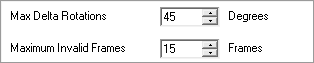
Max Delta Rotations
|
The maximum number of degrees that a rigid body rotation can rotate between frame. If the rotational motion is more than the max, the rigid body position is flagged as invalid.
|
Maximum Invalid Frames
|
Specifies the maximum number of frames that the rigid body can be invalid (not seen) before the Rotation Consistency Check is being reset.
When the Check is being reset, Maximum Invalid Frames divided by 2 is recorded and validated before a body is returned as valid. This will also happen when a body is first encountered after streaming has started. However, in this case, the Maximum Invalid Frames is divided by 4.
|
|
3D Boundary Check
|
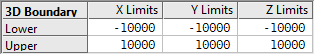
Defines the boundaries of the 3D measurement volume in system units (currently mm only). Any 3D markers found outside the 3D boundary will be discarded. This can be useful to eliminate 3D points that are not part of the current measurement.
|

