How make your wand Kit


|
How make your wand Kit |
|
|
The calibration kit for the dynamic wand calibration method consists of a reference structure with 4 markers and a wand with 2 markers. The size of the wan and the structure depends on your Field Of View (FOV). It is recommended to use a wand that is approximately 30-60% of the FOV.
The wand
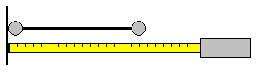
A wand can be created by attaching two round markers on either end of a metal or wooden rod. The diameter of the rod should not exceed 50% of the marker diameter. Wand length is given by the distance between centroid's of the two markers. To get accurate length, measure the distance from the outer end of one marker to the inner end of the second marker as shown in the figure that follows.
The reference Structure
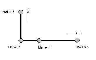
The reference structure is normally shaped as L with four markers on it as shown below.
The four markers are used to define the orientation of the global coordinate system during system calibration. In most cases positive X is aligned with the long arm and positive Y is aligned with the short arm.
To make the reference structure, 4 markers can either be attached to a board or an L shaped structure such as a carpenters square. The markers can even be placed on the floor and removed or covered up during the trials. Please refer to the above figure for marker placement.
The distance between marker 1 and 4 should be 20-40% of the distance between marker 1 and 2. For example, if the distance between marker 1 and 2 is 600 mm, then place marker 4 about 200 mm from marker 1. When you have placed the markers as above, measure the distance between marker1 and 2 (long arm) and the distance between marker 1 and 3 (short arm). Note that marker 3 must be placed perpendicular to the marker 1-2 vector.
|